TERMINAL TORQUE
Terminal connections must be properly torqued. Rolls VB-Series LFP drop-in batteries using M8 fasteners should be torqued to 6Nm.
DO NOT OVERTORQUE: In the event of a damaged terminal, do not attempt to repair the terminal. Do not use the battery if the recommended torque cannot be met.
INSTALLATION
VB-Series LFP drop-in batteries must be installed upright and may not be installed on a side or upside down. Rolls LFP drop-in batteries must be installed in an indoor space out of direct sunlight.
All installations should consider the ambient temperature. If installed in a region with freezing temperatures or extreme heat, special care should be given. Not all -20°C (-4°F) environments are created equally; heat sinks, airflow and other conditions may limit the effectiveness of internal heaters. Insulation and battery boxes should be used where extreme cold is a concern. Rolls VB-Series LFP drop-in batteries will activate heating when charged below 0°C (32°F) and will not be available for charge until the internal cells have reached a temperature over 0°C (32°F). The batteries cannot be charged or discharged below -20°C (-4°F) and bypassing the BMS to do so will severely degrade the internal cells. Similarly, operation above 55°C (131°F) will negatively impact longevity, performance, and safety.
Waking up the Battery
If you have just received your battery, it may have entered a low power sleep mode during transit. In this state, the Bluetooth receiver will be off, and the apparent voltage will be between 2V-10V, waiting to sense an external device. For VB-Series LFP drop-in models, connect a charger or load (of greater than 1A) to “wake up” that unit and enable charging, discharging, and a Bluetooth connection.
During normal operation, sleep mode will activate if the battery has not detected current for 24 hours, or if a low voltage condition is observed, it will enter sleep after 5 minutes. It is recommended to recharge an overdischarged battery within 24 hours to avoid potentially unrecoverable deep discharge conditions.
CABLE CONNECTIONS
All cable connections should be adequately sized, insulated, and undamaged. Connectors should be clean and properly mated with the battery terminals to ensure a secure and low resistance connection. Terminal connections should be torqued to the recommended specification in TERMINAL TORQUE. Although Rolls VB-Series LFP drop-in batteries do not require maintenance such as cell inspection & watering, routine inspection of cabling and terminal connections should be performed semi-annually. Double check torque specification and that lugs cannot be rotated after installation. If the batteries are installed in a high vibration environment, this should be done more frequently.
Note: Undersized or improperly insulated cables may lead to cable and/or battery damage, charging issues, terminal heating, or fire. The gauge table above is provided for reference only. Always refer to the connector and wire manufacturers’ specifications prior to purchase and installation. Wire area measurements are rounded down from AWG table as reference. For example, 4/0 AWG has a cross-sectional area of 107mm2, so the nearest available size is 120mm2.
Like lead-acid batteries, connecting devices (like batteries, inverters, chargers, MPPTs, etc.) at different voltages can result in large current spikes and arcing. Sparking may occur if you are connecting a power supply or charger with high output capacitance, or a discharged inverter with high input capacitance, as the battery rapidly charges the components in the device. Connecting terminals quickly and decisively is recommended for the least component wear and tear or using in-line overcurrent protection devices such as an open breaker, to eliminate arcing.
BMS PROTECTION SUMMARY
Rolls LFP drop-in batteries include a built-in battery management system (BMS) which offers protection in conditions where the battery voltage, current or operating/cell temperature may be unsafe or damaging for the internal cells. The switch architecture of the BMS allows charge and discharge to be stopped independently. Under these undesirable operating conditions, the internal BMS can independently interrupt charge or discharge, or disconnect it fully, as required.
*Temperatures outside of the ideal operating range require a reduction in charge/discharge current for optimal battery life.
The BMS also has cell-balancing functionality to balance each internal cell to the same state-of-charge, enabling the full pack capacity. However, this is not sufficient to balance severely imbalanced cells with a substantial state-of-charge (SOC) difference, see BATTERY VOLTAGE – CONNECTING IN SERIES/PARALLEL.
CONNECTION LIMITS
 CAUTION
Battery strings must be independently fused. Fuse rating must be appropriate for voltage of battery string and current limit of connected components.
Note: Rolls VB-Series drop-in models cannot be mixed. Batteries should only be combined in the same capacity, and voltage, from the same product line.
Note: For lithium batteries, parallel batteries are preferred over series strings. Rolls VB-Series drop-in models perform best when connected in parallel. Choosing drop-in batteries at a voltage to match your external equipment is recommended, especially in colder environments where heating functions will be used.
CONNECTING IN SERIES
Rolls VB-Series 12V and 24V LFP batteries may be combined in series strings to achieve higher operating voltages by connecting the positive terminal of one battery to the negative terminal of the next battery. Don’t connect different voltages in series. For example, do not connect a 12V and 24V battery to reach 36V, use three (3) 12V batteries instead, or a single 36V battery.
Note: 36V and 48V models may NOT be connected in series.
Example Series Configurations
Note: Do not connect batteries in strings above 48V nominal.
CONNECTING IN PARALLEL
You may combine Rolls VB-Series LFP drop-in batteries of the same model together in up to four (4) parallel strings to increase system capacity.
Refer to the example below showing eight (8) 12V LFP drop-in batteries connected in a 48V configuration; four (4) connected in series and two (2) parallel strings (4S2P). Up to four (4) 48V parallel strings of 12V or 24V LFP drop-in models may be connected. Parallel string configurations greater than 48V in series, four in parallel (4S4P or 2S4P) are not supported currently.
Note: When connecting parallel strings of Rolls VB-Series LFP drop-in batteries of the same model, the recommended current limit increases proportional to the number of parallel strings.
Note: Busbars should be used for all configurations with parallel strings. If an installation cannot accommodate a positive and negative busbar, external connections should be staggered as depicted below:
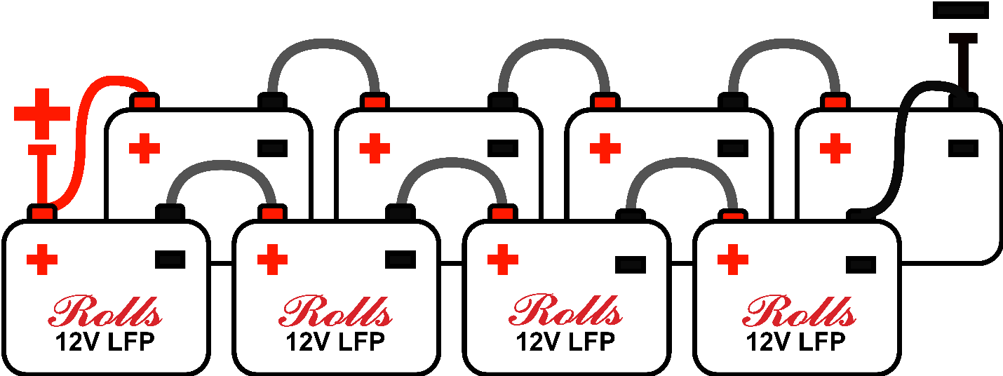
Note: Strings are independent. External connections should be staggered, i.e., the positive lead is connected to string one, whereas the negative lead is connected to string two.
Note: Keep cabling the same resistance (gauge and length) between batteries and strings to ensure proper current sharing. Attempt to minimize length to reduce the magnitude of inductive voltage spikes at the battery.
Note: Battery strings must be independently fused. Fuse rating must be appropriate for voltage of battery string and current limit of connected components.
 CAUTION
Failure to follow the following safety instructions may result in personal injury or damage to the equipment.
Rolls VB-Series LFP drop-in batteries should be fully charged in parallel before connecting for series cycling, see above.
BATTERY VOLTAGE - CONNECTING IN SERIES/PARALLEL
For initial balancing prior to connecting batteries in series, each battery should be connected in parallel and fully charged (or charged individually) using a 2-stage CC/CV charger at a reduced CV voltage corresponding to the low end of the acceptable charge range (see below), leaving the battery at the absorption/CV voltage for at least 24 hours.
If you are unable to charge the batteries individually, the voltage of each battery should be within 30mV (0.03V) before putting them in service. This will minimize the severity of a charge imbalance between batteries which results in reduced pack capacity. LFP batteries, even those with similar open circuit voltages may be at drastically different SOC, due to the flat relationship between open circuit voltage and SOC for LFP cells.
Although the BMS provides over-voltage protection to each cell, developing a charge imbalance between batteries is still possible. Disconnecting and fully charging each battery individually once per year if 1 or 2 parallel strings is used, or every 6 months in systems with 3 or 4 parallel strings, is recommended. If the batteries are cycled frequently at high charge/discharge currents this may be done more often.
Absorption time can also help with balancing. For a single string, absorption times of 20-30 minutes is recommended, or up to 60 minutes for 4 strings. See 3-STAGE CHARGING - LEGACY LEAD-ACID SYSTEMS, INVERTER/CHARGER HARDWARE for more information on using legacy chargers with VB-Series LFP.
BLUETOOTH/APP CONNECTIVITY




Waking up the Battery
This is also discussed above in Waking up the Battery.
If you have just received your battery, it may have entered a low power sleep mode during transit. In this state, the Bluetooth will not broadcast a signal your device can connect to. For VB-Series LFP drop-in models, connect a charger or load to “wake up” that unit and enable a Bluetooth connection.
Establishing a Connection
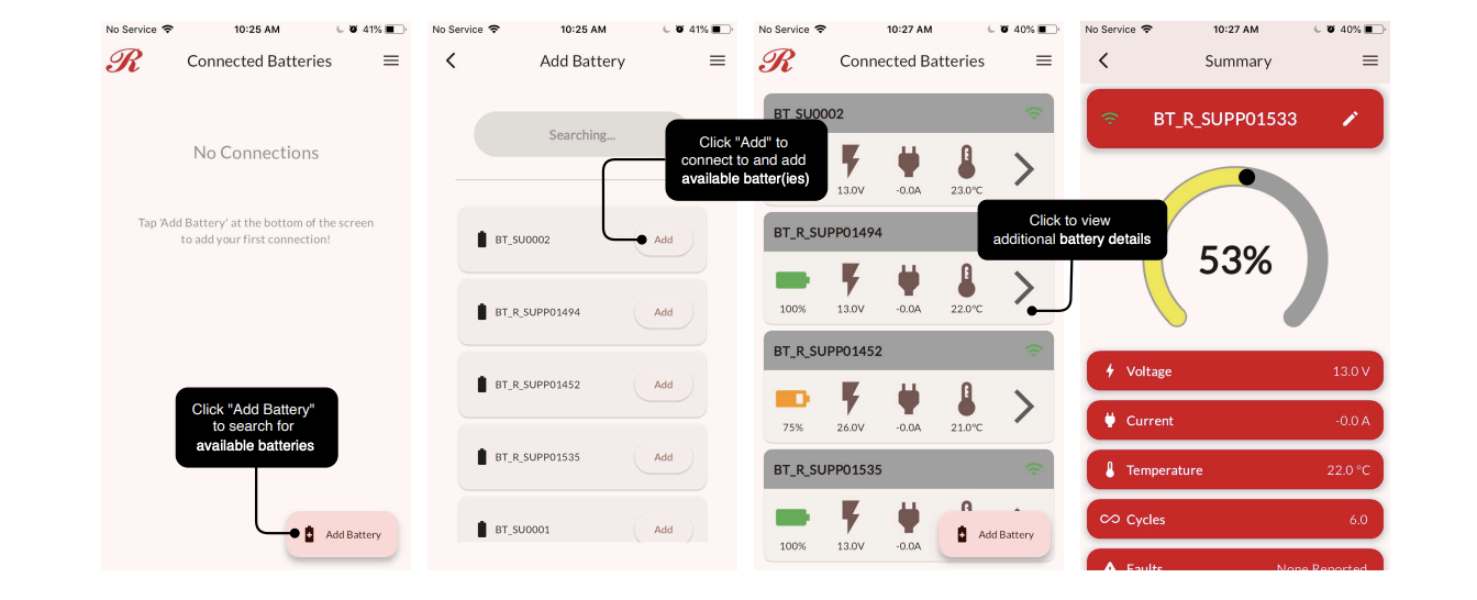
Select “Add Battery” to initiate a new battery connection. Using Bluetooth, your device will then search for batteries within signal range. Available batteries will be listed as shown above. If your battery cannot be found, try waking up the battery (above), and ensure no devices which may block or interfere with a wireless signal are nearby. All batteries within range will be listed by the app. If you have multiple batteries to connect to, consult the lasered serial number on the side of the unit to keep track of each battery. Click “Add” for the selected batter(ies). Consider installing them in ascending order, or an order you can easily remember. Bluetooth names may not be sequential but will be unique. Once connected, a battery may be selected from the Connected Batteries list to viewadditional details.
Dashboard & Support Screens
The main Dashboard screen has a display of estimated state-of-charge (SOC), the connected battery (device ID?), battery voltage, current, internal cell temperature, and any active fault codes.
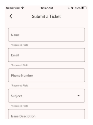
Using the app, you can also submit a support ticket. When submitted, you will receive email confirmation and be contacted by a member of our Technical Support team regarding your issue. Please provide as much relevant information in your ticket as possible so they can better assist you.
Was this article helpful?
That’s Great!
Thank you for your feedback
Sorry! We couldn't be helpful
Thank you for your feedback
Feedback sent
We appreciate your effort and will try to fix the article