BATTERY CHARGING
Although a lithium-specific charger is recommended, Rolls VB-Series LFP drop-in models are compatible with many common lead-acid battery chargers which operate at the same nominal voltage of the pack. The acceptable charge voltage range and recommended & maximum continuous charge currents are specified on the product label for reference.
Rolls VB-Series LFP drop-in batteries may cycle or be stored in a partial state of charge (PSOC). Rolls VB-Series LFP drop-in batteries should be cycled from 100% state-of-charge (SOC) [0% depth of discharge (DoD)], to 20% SOC [80% DOD] for optimal cycle life. To prevent over-discharge, the BMS will disconnect the battery when the low voltage cut-off is reached, protecting the battery from over-discharge.
Note: Chargers that require the detection of voltage at the battery terminals to charge may fail to wake the VB-Series LFP drop-in battery from a state of under-voltage protection or sleep.
Note: LFP cells do not need maintenance charges like equalization, pulse charge, overcharge, or any others typically recommended or required for lead-acid batteries.
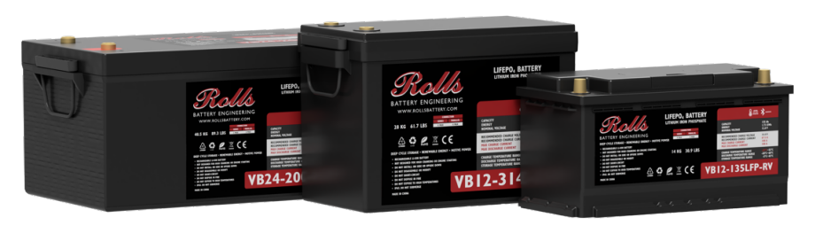
Note: The recommended and maximum continuous charge & discharge currents are specific to each VB-Series LFP drop-in model. These are determined by capacity, cell and BMS technology. Model-specific information is provided on the product label.
CHARGING GUIDELINES
Rolls VB-Series LFP drop-in batteries may be charged in a 1, 2, or 3-Stage charge profile, shown below. The specifics and recommended setpoints for these charge regimes are explained in this section, with the recommended charge profile being a 2-Stage charge.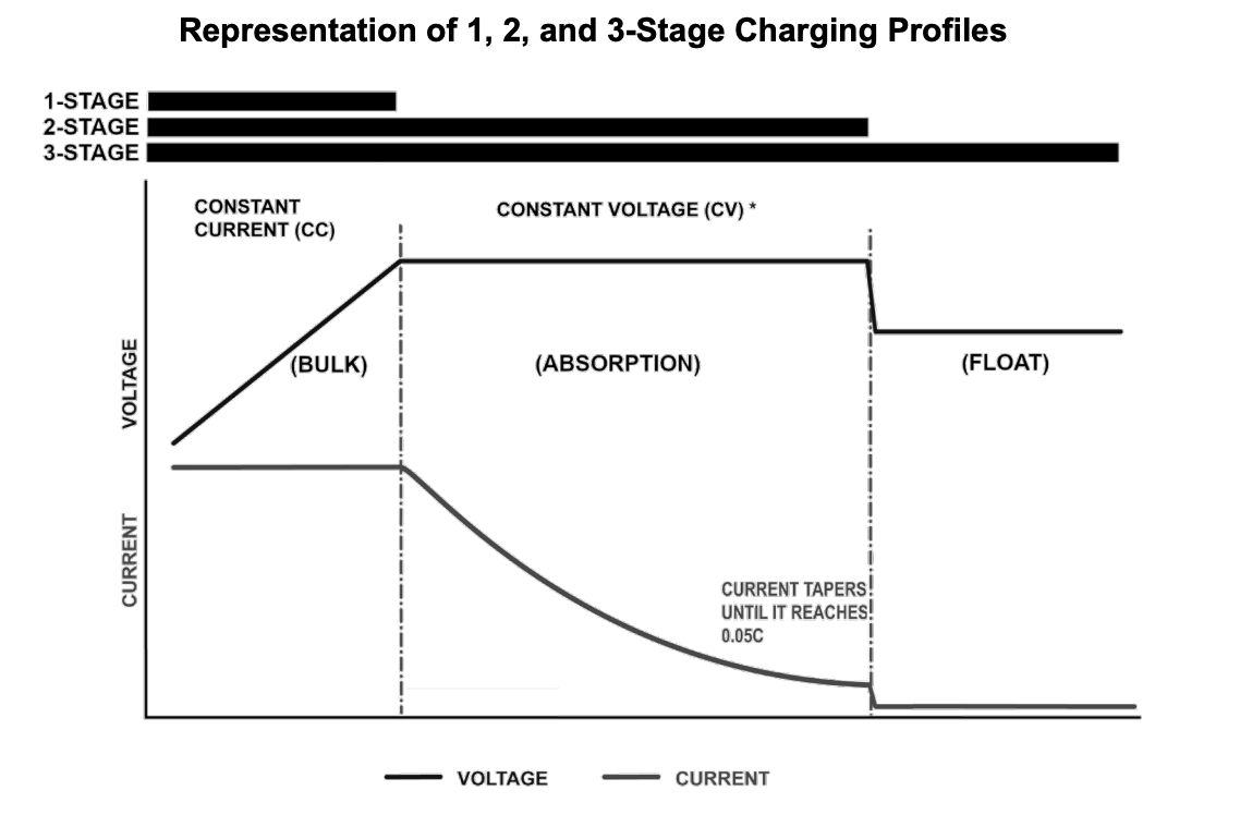
Representation of recommended 2-Stage Constant Current/Constant Voltage (CC/CV) charging. The dotted line represents the transition from CC to CV when the voltage limit is reached. Once the battery reaches the constant voltage limit, the battery is held by the charger at this voltage until the current decreases to 0.05C. At this point the battery is at 100% state-of-charge (SOC). Any current continuing to flow in the float stage is attributable to balancing activity of the BMS.
CHARGING SOURCE: ALTERNATOR
Alternators in automotive, marine, and RV applications are typically not designed to tolerate the sudden load changes that can occur during a rapid open-circuit event. This condition may occur if the battery bank disconnects due to a fully charged state, temperature limit, or overcurrent protection triggered by the BMS. When the load is suddenly removed, the alternator’s field excitation can produce a high-voltage transient at the output, potentially damaging internal rectifiers or voltage regulation circuitry. To mitigate this risk, it is recommended to install an alternator protection device or intermediary DC charge controller to isolate and protect the alternator in the event of a battery disconnection.
CHARGING SOURCE: LEAD-ACID BATTERY CHARGER
Customers may choose to replace lead-acid batteries with lithium models. Most lead-acid battery chargers may be used to charge Rolls VB-Series LFP drop-in models so long as the charger is properly configured to operate within the recommended charge current and voltage limits.
The pre-programmed voltage settings for AGM or OPzV GEL models may be in line with the recommended LFP drop-in charge voltage settings and may sometimes be used if direct voltage control is not possible for your charger. However, flooded batteries often require higher charge voltage settings than sealed models. If left configured for charging flooded batteries, the higher charge voltage can trigger the BMS to restrict charging to protect the battery, effectively resulting in a 1-stage charge. If this occurs repeatedly, or the charger cannot be configured at a lower charge voltage, it may be necessary to replace the charger for optimal balancing.
1-STAGE CHARGING – CC (CONSTANT CURRENT)
When charging with a single-stage constant current charger, charge at the recommended charge current, by operating temperature, until the battery reaches its termination voltage.

Note: 1-Stage CC Charging may be required if charging from a source which is not efficient to run at lower power, such as a generator. However, it may only charge the battery to 90-95% SOC and provide very little time to balance cells. For these reasons, 2-Stage CC/CV charging is recommended to ensure the battery reaches full SOC.
2-STAGE CHARGING – CC/CV (CONSTANT CURRENT/CONSTANT VOLTAGE)
When charging with a two-stage constant current/constant voltage (CC/CV) charger, charge at the recommended charge current, by operating temperature, until the battery reaches the “absorption” voltage or constant voltage (CV) limit. The charger then holds the battery at CV until the charge current decreases to ≤0.05C (termination current).
The recommended absorption (constant voltage) voltage is shown below. If the charger has a pre-set voltage setting or cannot be programmed, an absorption voltage in the range below is also acceptable. Note: lower voltage will lead to longer charge times.

Note: If charge time is not a concern within your system architecture, reducing the absorption voltage will increase charge time, but allows the BMS more time to ensure all cells remain balanced. As batteries age, small changes in manufacturing or due to uneven wear may present themselves, requiring more time to maintain balance.
3-STAGE CHARGING - LEGACY LEAD-ACID SYSTEMS, INVERTER/CHARGER HARDWARE
When programming an inverter/charger or charge controller equipment using a 3-stage charge sequence (2-stage with an additional “float voltage” after the charge is terminated), the following charging parameters should be programmed to properly charge Rolls 12V, 24V, 36V & 48V VB-Series LFP drop-in batteries:

Temperature Compensation: If the inverter/charger or charge controller uses temperature compensation this should be turned off when charging Rolls VB-Series models. Turn off the temperature compensation settings and disconnect the sensor to ensure the correct voltage regulation from the charging device.
Equalization: Equalization should never be used; elevated charge voltages are unacceptable for LFP batteries and will simply lead to the BMS disconnecting the charging path. It should be turned off, or the equalization voltage setpoint should be reduced to the appropriate system float voltage, above.
Some charger models may require additional firmware, programming, or parameters. Please contact your inverter/charger or charge controller manufacturer for assistance with these settings, if required.
CHARGING TEMPERATURE
Due to the chemistry of LFP cells, these batteries cannot accept high charge current at low operating temperatures without cell damage and permanent capacity loss.
Rolls VB-Series LFP drop-in batteries may be safely charged between 0°C to 55°C (32°F to 131°F), and as low as -20°C (-4°F) with heating active (charge may be delayed as the heater warms the battery). However, because cycle wear is accelerated below 10°C (50 °F), the charge should be limited to 0.2C (20% of battery capacity) for optimal longevity. Similarly, at high temperatures, charge current should be limited to 0.2C when operating at temperatures from 35°C to 55°C (95°F to 131°F) as noted below.
Rolls VB-Series LFP drop-in batteries may be charged at lower temperatures due to their internal heating. This allows them to compensate for external temperatures down to as low as -20°C (-4°F). If the batteries are typically charged at low temperatures [-20-0°C (-4-32°F)], proper insulation is required to keep the batteries at their warmed temperature. It is recommended to avoid series configurations when heating will be commonly used or consider auxiliary balancing such as a multibank charger or external charge shuttlers. LFP batteries without battery-to-battery communication always perform better in parallel.
To maintain optimum performance and durability of Rolls VB-Series LFP batteries, the following charge current limits should be followed:
The recommended and maximum continuous charge current is specified for each VB-Series LFP drop-in model as a function of capacity, cell and internal BMS. This information is noted in the model specifications and on the battery label.
Was this article helpful?
That’s Great!
Thank you for your feedback
Sorry! We couldn't be helpful
Thank you for your feedback
Feedback sent
We appreciate your effort and will try to fix the article