BUSBAR CONNECTIONS – Even Number of Modules
NOTE: Depending on the number of modules, a different busbar connection order is recommended to accommodate the stacked busbar and placement of busbar combiners, and to ensure all connections are secure. Please follow the appropriate guidelines for your configuration.
These detailed instructions below outline the steps required to install positive and negative terminal connections from the top of the module stack to the bottom, reducing the amount of bolting and unbolting if an incorrect order is used. You may choose to install the busbars in the order you prefer. However, it is required that the busbar combiners and external connections are staggered, and that busbars are properly installed parallel to the terminals with no angled busbar connections in the system.
Note: Torque terminals after all busbars have been installed.
Even Numbered Configurations: Positive Terminals
Before Starting Connection
● Double check that all module side-mounted breakers are in the OFF position.
● To begin installing terminal busbars, first remove all positive & negative terminal bolts from each MODULE.
Depending on the number of modules to be installed, follow the steps outlined below for
installation of positive terminal busbars.
| # Modules | Initial Step | Next Steps |
| 8 Modules | Install two positive busbars between MODULE 8 and MODULE 7, fixing only the bolts on MODULE 8. Do not torque. | Proceed to steps 1-7 below |
| 6 Modules | Install two positive busbars between MODULE 6 and MODULE 5, fixing only the bolts on MODULE 6. Do not torque. | Proceed to steps 3-7 below |
| 4 Modules | Install two positive busbars between MODULE 4 and MODULE 3, fixing only the bolts on MODULE 4. Do not torque. | Proceed to steps 5-7 below |
| 2 Modules | Install two positive busbars between MODULE 2 and MODULE 1, fixing only the bolts on MODULE 2. Do not torque. | Proceed to step 7 below |
1. Place the two positive busbars between MODULE 7 and MODULE 6 in front of the
busbars for MODULE 7.
a. Tighten the bolts on the busbars on MODULE 7. Do not torque. You should have 2 busbars stacked on each positive terminal of MODULE 7.
2. Place the two positive busbars between MODULE 6 and MODULE 5 behind the
previously placed busbars.
a. Tighten the bolts on the busbars on MODULE 6. Do not torque. You should have 2 busbars stacked on each positive terminal of MODULE 6.
3. Place the two positive busbars between MODULE 5 and MODULE 4 in front of the existing busbars on MODULE 5.
a. Tighten the bolts on the busbars on MODULE 5. Do not torque. You should have 2 busbars stacked on each positive terminal of MODULE 5.
4. Place the two positive busbars between MODULE 4 and MODULE 3 behind the previously placed busbars.
a. Tighten the bolts on the busbars on MODULE 4. Do not torque. You should have 2 busbars stacked on each positive terminal of MODULE 4.
5. Place the two positive busbars between MODULE 3 and MODULE 2 in front of the existing busbars on MODULE 3.
a. Tighten the bolts on the busbars on MODULE 3. Do not fully torque. You should have 2 busbars stacked on each positive terminal of MODULE 3.
6. Place the positive busbars between MODULE 2 and MODULE 1 behind the previously placed busbars.
a. Tighten the bolts on the busbars on MODULE 2. Do not fully torque. You should have 2 busbars stacked on each positive terminal of MODULE 2.
7. Finally, before installing the bolts on MODULE 1, affix one busbar COMBINER in front of the positive busbars on MODULE 1. (as shown in the illustration below)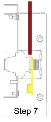
Even Numbered Configurations: Negative Terminals
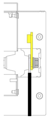
Connect the Negative busbars following the same sequencing as busbars as outlined above, working from the top module to the bottom, beginning with the busbar COMBINER installed in front of the two negative busbars on the top MODULE (8, 6, 4, or 2). (as shown in the illustration below)
Follow torquing directions in TERMINAL TORQUE and external connector instructions in EXTERNAL CABLE CONNECTION when connecting external equipment.
Was this article helpful?
That’s Great!
Thank you for your feedback
Sorry! We couldn't be helpful
Thank you for your feedback
Feedback sent
We appreciate your effort and will try to fix the article