OVERVIEW
This document provides information on the integration of Rolls S48-100LFP STACK-LV – S48-800LFP STACK-LV ESS with LUXPOWERTEK Hybrid Inverters via RS-485 communication. The integration covers, but is not limited to, the following components:
Refer to www.rollsbattery.com for the most recent version of these documents.
The following guide references instructions from the inverter manufacturer. Always verify these settings against current versions of the manufacturer’s documentation and any additional settings necessary for other system components. Rolls Battery accepts no responsibility for any damage or issues that may occur from the use of this material.
BATTERY CURRENT OPERATING LIMITS
Maximum Battery and ESS Operating Limits
Different system configurations will change the acceptable operating limited. The ESS should not be operated outside these operating limits. The BMS will open its internal switch and disconnect the battery in charge and/or discharge if any of these limits are exceeded. Repeated operation outside of posted limits will void your warranty.
Note: Intentional bypassing of a BMS to operate a battery outside its maximum and minimum limits voids warranty and may lead to safety concerns. Refer to the Manual and Label for a full list of operating limits.
Minimum Battery Capacity
Using large solar arrays with ESS that are too small may exceed the operating limits of the ESS which would potentially trigger BMS over-current protection. Battery capacity must be sized to accommodate the maximum charge current of the system, or the charging devices must be adjusted to limit charge output below the operating limit of the installed batteries. This value is determined by summing the charge capacities of all inverter/chargers and solar charge controllers in the system. Additionally, the ESS must be sized with a peak current limit that supports the surge requirements demanded by the DC loads (including inverter). Ensure that the sum of peak currents of all devices on the DC bus is less than or equal to the sum of the ESS peak current values.
ROLLS S48-100LFP STACK-LV CLOSED LOOP INTEGRATION WITH LUXPOWERTEK EQUIPMENT
LXP Series
This guide outlines the setup process to connect Rolls S48-100LFP STACK-LV batter(ies) with the LXP-LB-US 12K inverter firmware version: FA1.0, following LXP-LB-US-12K-User-Manual-2025.4.14-1 (UM-LXPUS02001E01). If your current product version varies, refer to the LUXPOWERTEK website or contact LUXPOWERTEK for additional support and information.
Ensure the S48-100LFP STACK-LV BMS is activated by pressing the on/off button. The screen and RUN light will be on.
Ensure all S48-100LFP STACK-LV batteries are properly interconnected via Link in/out ports and set up properly for DIP switch addresses before connecting the external CAN bus communication connections.
Refer to Appendix B in S48-100LFP STACK-LV Battery Installation Guide. Connect the battery MODULE 1 RS-485 port to the inverter BAT COM port using a straight cable

NOTE: The EXTERNAL COMM CABLE supplied with the LFP STACK BASE+TOP ASSEMBLY or any straight ethernet cable is directly compatible with LUXPOWERTEK LXP inverter models using RS-485. For further pinout details, please reference at CAN COMMUNICATION below.
4. The inverter is automatically configured out of the box for compatibility, simply connect the battery as above, wait several minutes for startup, and verify connectivity by selecting the icon and selecting Battery. The readout should show battery parameters such as requested charge and discharge current, battery voltage, current, and temperature, etc.

NOTE: Screen shown with settings typical of single module ESS (S48-100LFP STACK-LV) setup. This capacity is considered too low for the LXP-LB-US-12K inverter.
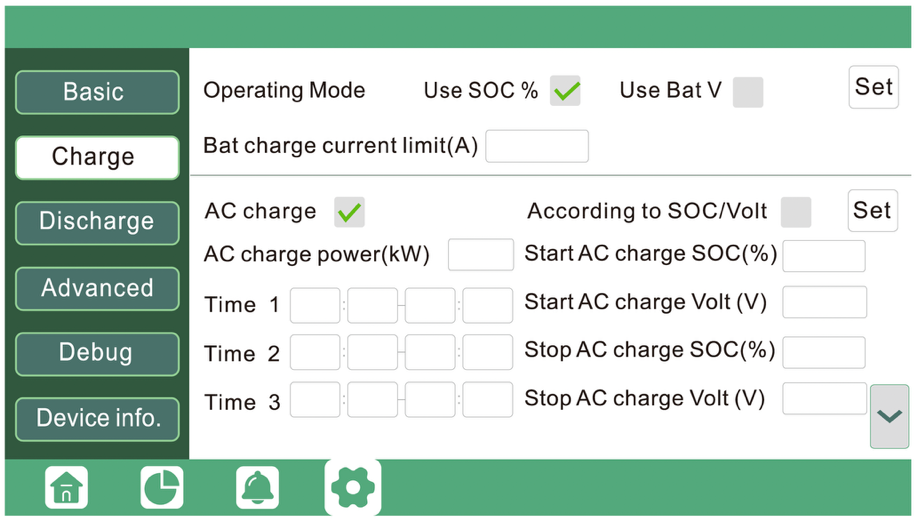
5. If the battery needs to be reconfigured, select the icon, then Advanced, then in the bottom right. Ensure Battery type is set to 2:Lithium, and Lithium brand is set to 6: Lithium_6. If necessary, correct these values and hit Set to confirm.

6. After hitting the Charge menu, users may set the Bat charge current limit (A) based on their system configuration.
Note: A more conservative limit may be used in cold climates or to maximize cycle life.
7. Then, users may set the backup parameters by hittingin the bottom right. Under the “Lead-Acid” Menus to 57.0V for Absorb voltage(V) and Float voltage(V), then hit Set.

8. After hitting the Discharge menu, users can then set the Discharge current limit (A) based on their system configuration. A more conservative limit may be used in cold climates or to maximize cycle life.
9. Users may set the cut-off parameters by ensuring that “Use SOC%” is checked, then setting “Lead-Acid” Menus to 20.0% for On-grid Cut-off(%) and Off-Grid Cut-off(%), for best cycle life. Then hit Set to confirm these values.

10. Users may choose to update configuration parameters in Charge and Discharge menus, including charge priority, grid charge, time or use and load shedding, generator start and stop, etc. Refer to the LXP-LB-US-12K-User-Manual for the full scope of setup options.
SNA Series
This guide outlines the setup process to connect Rolls S48-100LFP STACK-LV batter(ies) with the EG4 6000 XP (SNA US 6K) inverter, following EG4 6000 XP OFF-GRID INVERTER User Manual (V1.6.9). If your current product version does not align with this document, refer to the EG4 or LUXPOWERTEK website or contact EG4 or LUXPOWERTEK for additional support and information.
The following steps are physically performed on the system devices or related to their interconnectivity.
Activate the BMS in each S48-100LFP STACK-LV batter(ies) by pressing the on/off button. The screen and RUN light will be on.
Ensure all S48-100LFP STACK-LV batteries are properly interconnected via Link in/out ports and set up properly for DIP switch addresses before connecting the external CAN bus communication connections.
Refer to Appendix B in S48-100LFP STACK-LV Battery Installation Guide.
Connect the battery MODULE 1 RS-485 port to the inverter BAT COM port:

NOTE: EG4 6000 XP model shown for reference. For other models, please refer to the applicable EG4 or LUX Power installation guide.
NOTE: The EXTERNAL COMM CABLE supplied with the LFP STACK BASE+TOP ASSEMBLY or any straight ethernet cable is directly compatible with EG4 and LUX Power SNA inverter models. For compatibility check with EG4 or LUX Power SNA inverters, please reference at CAN COMMUNICATION below.
The following setup steps are performed on the display of the device:
Turn on the Device → Go to Device Settings list on the Main screen by pressing the Enter button for 3s→ Select Battery page [3] → push Enter.

Select batteries type as Li-ion → push Enter.
Select 06 for BAT.Brand → push Enter.
Push Enter again. You will be redirected to the Settings list.
Select 1C: Maximum Charge Current page [6] → push Enter
 Set Total Charge Current (1c) based on your Rolls Battery Model, and the max charge current value. (see BATTERY CURRENT OPERATING LIMITS)
Push Enter to register the Total Charge Current value.
Set AC Charge Current (1ac) to your desired AC charge limit.
Rolls recommend set AC Charge Current to the same as the Total Charge Current (1c).
Push Enter to register the AC Charge Current value.
If you wish to use a generator to charger your Rolls battery, set Generator Charge Current (1gc) based on the generator current input. If you don’t have a generator set to 0.
Push Enter to register the Generator Charge Current.
Push Enter again. You will then be redirected to the Settings list.
Select 1d: Maximum Discharge Current page [9] → push Enter
 Set Total Discharge Current (1d) based on your Rolls Battery Model, and the max discharge current value. (see BATTERY CURRENT OPERATING LIMITS)
Push Enter to register Total Discharge Current value.
Push Enter again. You will then be redirected to the Settings list.
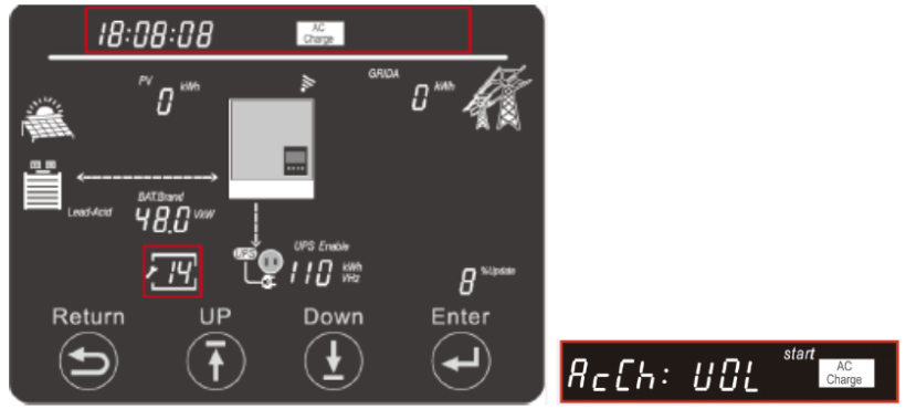
Select: Discharge Control Type page [10] → push Enter
 Select VOL as the trigger for battery discharge
Push Enter to register.
Push Enter again. You will then be redirected to the Settings list.
Select: CutOFF Voltage/SOC [11] → push Enter
 Select Cutoff VOL.
Enter 44.6 V.
Push Enter to register.
Push Enter again. You will then be redirected to the Settings list.
Select: Eod: Battery Discharge Cutoff [12] → push Enter
 Enter End of Discharge Cutoff Voltage.
Rolls recommended to Enter 47.0 V. Users may choose to alter this per their own requirements.
Push Enter to register.
Note: Eod values will set the lower end of your battery discharge range.
Push Enter again. You will then be redirected to the Settings list.
Select: AC Charge Setting [14] → push Enter (If you have an Off-Grid system, please skip this step).
Note: This inverter offers 4 types of AC charging configuration, which are charge by Time, Voltage, SOC, Voltage and Time, SOC and Time. If you are on TOU set up, you should choose Voltage and Time or SOC and Time configuration.
Note: If you wish to limit your AC charging time using the Time configuration, please consult your local installer or utility provider for the optimal charging period. The following instructions will not demonstrate the Time configuration.
Select AcCh: VOL→ push Enter
Enter 55.2 V for AC Start Charging Voltage.
Push Enter to register.
Enter 57.0 V for AC End Charging Voltage.
Push Enter to register.
Note: AcCh End values will set the Upper end of your battery charge range.
Push Enter again. You will then be redirected to the Settings list.
Push Return to go back to Main Screen.
 You should see a Status Code :40 on the top right screen, indicating battery Off-Grid mode during this setup.
You should see Normal system status at this time.
Push Down until you can read battery status information, include voltage, SOC, and capacity.
Note: if you cannot read the battery status information, please recheck the wiring, port connection, BAT.Brand setup on the inverter.
The inverter setup process is now complete.
CAN COMMUNICATION
S48-100LFP STACK-LV RS-485 pinout is shown below.
| Plug Pin | Description | |
| 1 | RS-485-B | |
| 2 | RS-485-A | |
| 3-8 | (No Support) |

Note: The RS-485 pinout above enables connection to a LUXPOWER LXP or SNA; or EG4 inverter using a normal (“straight”) ethernet cable.
LUX Power SNA and EG4 inverters BAT COM port configuration is shown below.

ROLLS S48-100LFP STACK-LV OPEN LOOP INTEGRATION WITH LUXPOWERTEK ENERGY EQUIPMENT
Important Notice – Communication Configuration Impacts Manufacture Warranty
We highly recommend configuring your battery and inverter in closed-loop mode as your primary option. Closed-loop operation ensures optimal performance, enhances safety through real-time communication between the battery and inverter, and maximizes the lifespan of your battery system.
Use of an open-loop configuration poses unnecessary risks, including potential overcharge/over-discharge conditions, reduced efficiency, and lack of coordinated fault protection. Please be aware that operating in open-loop mode will impact your performance warranty coverage.
Was this article helpful?
That’s Great!
Thank you for your feedback
Sorry! We couldn't be helpful
Thank you for your feedback
Feedback sent
We appreciate your effort and will try to fix the article