VERSION HISTORY/CHANGELOG
OVERVIEW
This document provides information on the integration of Rolls S48-100LFP STACK-LV – S48-800LFP STACK-LV ESS with Growatt Inverters via CAN bus communication. The integration covers, but is not limited to, the following components.
Refer to www.rollsbattery.com for the most recent version of these documents.
The following guide references instruction from the inverter manufacturer. Always verify these settings against current versions of the manufacturer’s documentation and any additional settings necessary for other system components. Rolls Battery accepts no responsibility for any damage or issues that may occur from the use of this material.
CERTIFICATION INFORMATION


BATTERY CURRENT OPERATING LIMITS
Maximum Battery and ESS Operating Limits
Different system configurations will change the acceptable operating limited. The ESS should not be operated outside these operating limits. The BMS will open its internal switch and disconnect the battery in charge and/or discharge if any of these limits are exceeded. Repeated operation outside of posted limits will void your warranty.
Note: Intentional bypassing of a BMS to operate a battery outside its maximum and minimum limits voids warranty and may lead to safety concerns. Refer to the Manual and Label for a full list of operating limits.
Minimum Battery Capacity
Using large solar arrays with ESS that are too small may exceed the operating limits of the ESS which would potentially trigger BMS over-current protection. Battery capacity must be sized to accommodate the maximum charge current of the system, or the charging devices must be adjusted to limit charge output below the operating limit of the installed batteries. This value is determined by summing the charge capacities of all inverter/chargers and solar charge controllers in the system. Additionally, the ESS must be sized with a peak current limit that supports the surge requirements demanded by the DC loads (including inverter). Ensure that the sum of peak currents of all devices on the DC bus is less than or equal to the sum of the ESS peak current values.
*Peak discharge is calculated based on single device surge/overload power capability for 5 seconds. For more details, refer to the user manual for the specific Growatt model.
ROLLS S48-100LFP STACK-LV CLOSED LOOP INTEGRATION WITH GROWATT EQUIPMENT
NOTE: Before proceeding, please ensure the S48-100LFP STACK-LV - S48-800LFP STACK-LV internal physical connection steps have been followed as per the S48-100LFP STACK-LV Battery Installation Guide above.
This guide ONLY outlines the setup process when connecting Rolls S48-100LFP STACK-LV batter(ies) to with the SPF 3000TL LVM-US inverter (Firmware 24.10,24), following Growatt User Manual (Rev 1.0).
The following steps are physically performed on the system devices or related to their interconnectivity.
Ensure the S48-100LFP STACK-LV BMS is activated by pressing the on/off button. The screen and RUN light will be on.
Ensure all S48-100LFP STACK-LV batteries are properly interconnected via Link in/out ports and setup properly for DIP switch addresses before external CAN bus communication connections. See the Appendix B in the S48-100LFP STACK-LV Battery Installation Guide.
Connect the battery MODULE 1 CAN port to the CAN Terminals on the Auxiliary Terminal Block as showing below:
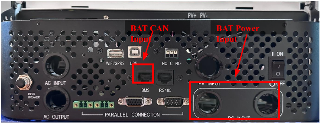
NOTE: The EXTERNAL COMM CABLE supplied with the LFP STACK BASE+TOP ASSEMBLY cable is NOT directly compatible with Growatt inverter Auxiliary Terminal Block. Please reference at CAN COMMUNICATION below to recut the inverter side of the RJ45 connector pin out.
Turn on the inverter and the battery.
Note: A battery communication fault alarm will be triggered at first time start, this is normal and processed with the following steps.
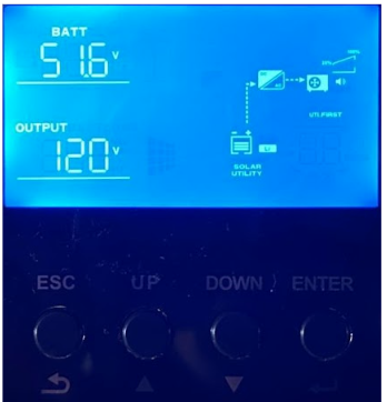
Push and hold the ENTER button under the screen for 3 seconds to enter the setting page.
Push the DOWN button under the screen unit reach setting page 05→ Push the ENTER button to select Battery Type
 Push the DOWN button until the battery type is set to LI.
Push the Enter button to confirm.

The screen will reach to setting page 36 automatically to set communication protocol.
Push the DOWN button until the communication protocol is set to L52 (Pylon CAN).
Push the Enter button to confirm.
Push the ESC button to return to the setting page.
Push the UP button under the screen unit reach setting page 12→ Push the ENTER button to set the lower end of battery SOC operation limit.
Note: Skip this step if you set the Output source to Utility first or SUB priority in Setting page 1 via Output priority. The minimum state of charge available for Growatt systems is 6%.

Push the DOWN button until the desired lowest battery SOC level before switch to utility when its available for grid-tied system, this will also be the battery shut down SOC level for Off-Grid systems.
For Grid-tied Systems (Solar first or SBU priority): Solar provides power to load first, if solar is not sufficient to power all the connected load battery will discharge to meet the load needs, if the battery drops to this pre-set SOC level or the low-level warning (send by rolls battery BMS), the utility will power the load.
Rolls recommends 20 %
For Off-Grid Systems (Solar first): Solar provides power to load first, if solar is not available or sufficient battery will discharge to meet the load needs, if the battery drops to this pre-set SOC level or the low-level warning (send by rolls battery BMS), the inverter will shut down at this point until solar or the generator changes the battery over the Upper end of the SOC operation limit.
Rolls recommends 30 %
Push the ESC button to return to the setting page.
Push the DOWN button under the screen unit reach setting page 13→ Push the ENTER button to set the Upper end of battery SOC operation limit.
Note: Skip this step if you set the Output source to Utility first or SUB priority in Setting page 1 via. Output priority.

Push the Up button until the desired highest battery SOC level before switch to the battery mode, all connected loads will be powered by solar and battery in this mode.
For Grid-tied Systems (Solar first or SBU priority):
Rolls recommends 40-45 %.
Note: For Grid-tied system, if the utility changes the battery to the pre-set value above, the inverter will switch to battery mode regardless of if utility is still available, and the charging process will be terminated.
For Off-Grid Systems (Solar first):
Rolls recommends 40-45 %.
Caution: For Off-Grid systems, if the battery is not charged to the set value above, the inverter will not switch to battery mode to enable discharge. To avoid this, ensure the charge source is appropriately sized, or lower this value to accommodate less than ideal conditions.
Push the ESC button to return to the setting page.
Push the DOWN button under the screen unit reach setting page 21→ Push the ENTER button to set the DC cut-off SOC limit.
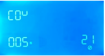
Push the Down button until the desired lowest battery SOC level before inverter cut-off battery energy supply.
For Grid-tied Systems: Rolls recommends 20 %
For Off-Grid Systems: Rolls recommends 20-25 %
Note: For Off-Grid systems, Rolls do not recommend setting the lower end SOC limit (step 6) same as the DC cut-off SOC limit, in case for over discharge the battery when no additional energy source to support the base load for the system.
Push the ESC button to return to the setting page
Push ESC to return to the System Status Page.
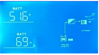
Push the DOWN button until reach the battery status Page.
Check Battery voltage and SOC read out is correct.
The inverter setup process is now complete.
CAN COMMUNICATION
S48-100LFP STACK-LV CAN pinout is shown below.
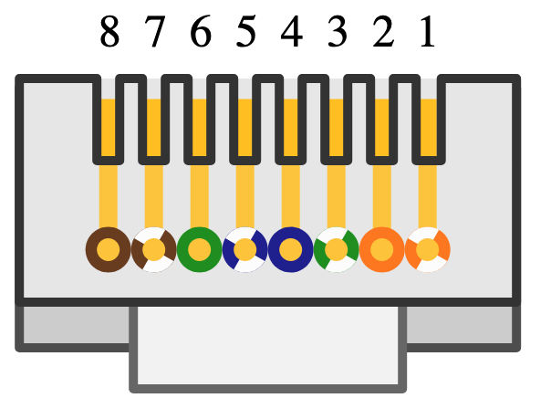
Growatt SPF 3000TL LVM-US CAN pinout is shown below.

ROLLS S48-100LFP STACK-LV OPEN LOOP INTEGRATION WITH GROWATT ENERGY EQUIPMENT
Important Notice – Communication Configuration Impacts Warranty
We highly recommend configuring your battery and inverter in closed-loop mode as your primary option. Closed-loop operation ensures optimal performance, enhances safety through real-time communication between the battery and inverter, and maximizes the lifespan of your battery system.
Use of an open-loop configuration poses unnecessary risks, including potential overcharge/over-discharge conditions, reduced efficiency, and lack of coordinated fault protection. Please be aware that operating in open-loop mode will impact your performance warranty coverage.
Was this article helpful?
That’s Great!
Thank you for your feedback
Sorry! We couldn't be helpful
Thank you for your feedback
Feedback sent
We appreciate your effort and will try to fix the article